Showing posts with label Projects. Show all posts

Wednesday, 18 May 2011

Controlling Home appliances through Infrared

RELATED POSTS:


VARIABLE REGULATED POWER SUPPLY--PROJECT

________________________________________________________________________________________________


A combined project by Abhishek, amit and me.


   Following is the list of parts or the components required to design this project:


  1. IR receiver module TSOP1738

  2. Transistor T1 (BC558)

  3. Decade counter IC CD4017 (IC1)

  4. LED1 (red)

  5. LED2 (green)

  6. Transistor T2 (BC548)

  7. Relay RL1, 5V, 100 ohm

  8. Diode 1N4007 (D1)

  9. R1 = 220K

  10. Bulb Holder

  11. Bulb

  12. R2 = 330 ohm

  13. R3 = 1K

  14. R4 = 330 ohm

  15. C1=100 uf,16V

  16. C2=0.1 uf

  17. 5V dc supply

  18. Soldering Iron ,Solder wire

  19. PCB Designing Material

  20. 2 Pin plug

  21. Wires


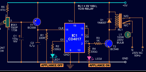
Connect this circuit to any of your home appliances (lamp,fan, radio, etc) to make the appliance turn on/off from a TV, VCD or DVD remote control. The circuit can be activated from up to 10 metres.The 38kHz infrared (IR) rays generated by the remote control are received by IR receiver module TSOP1738 of the circuit.

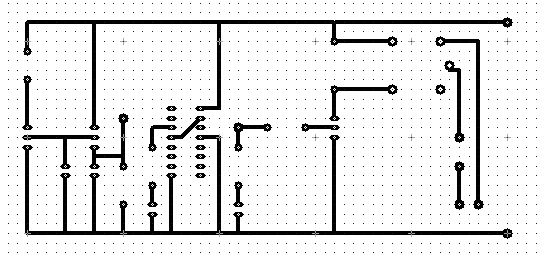
PCB LAYOUT :


CIRCUIT DIAGRAM:


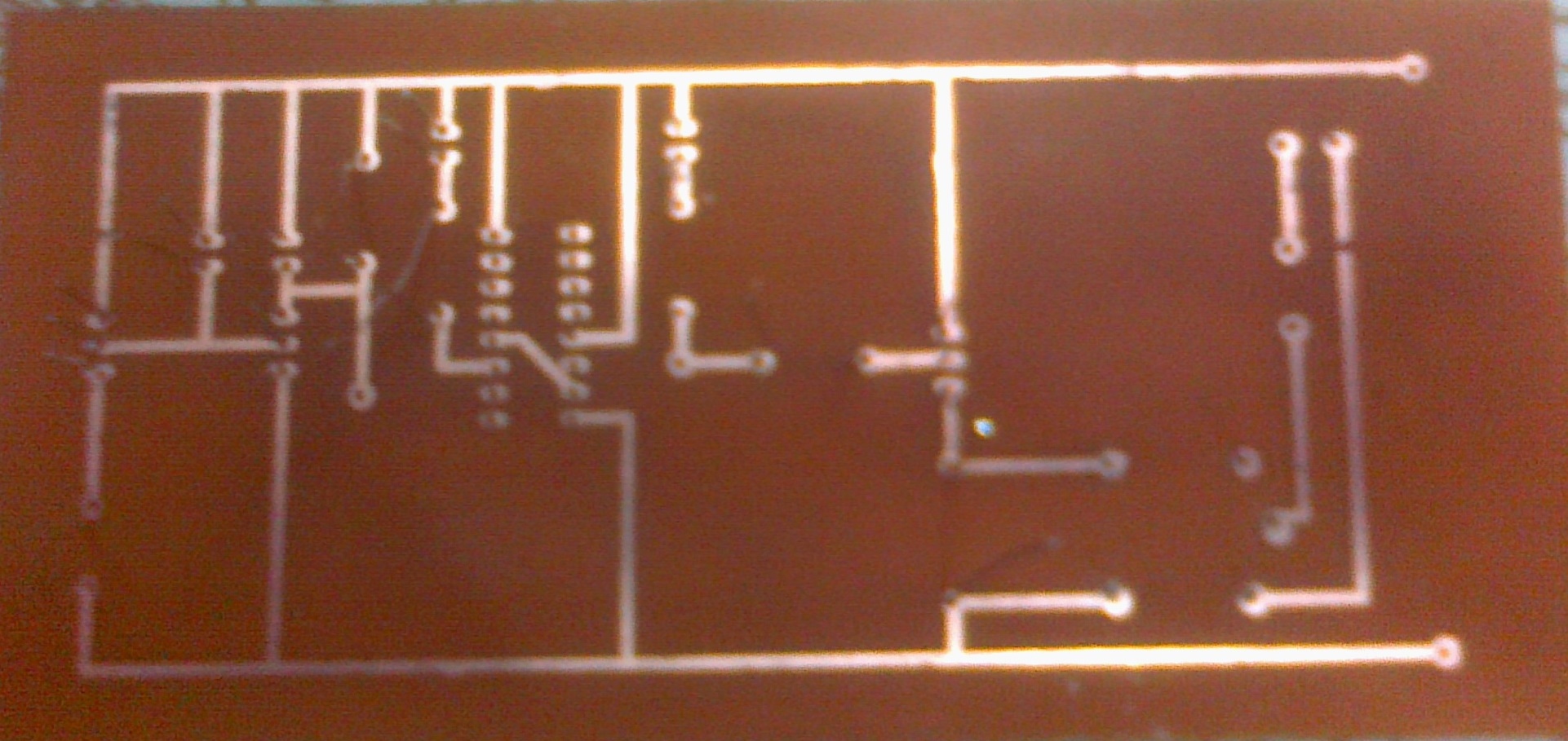
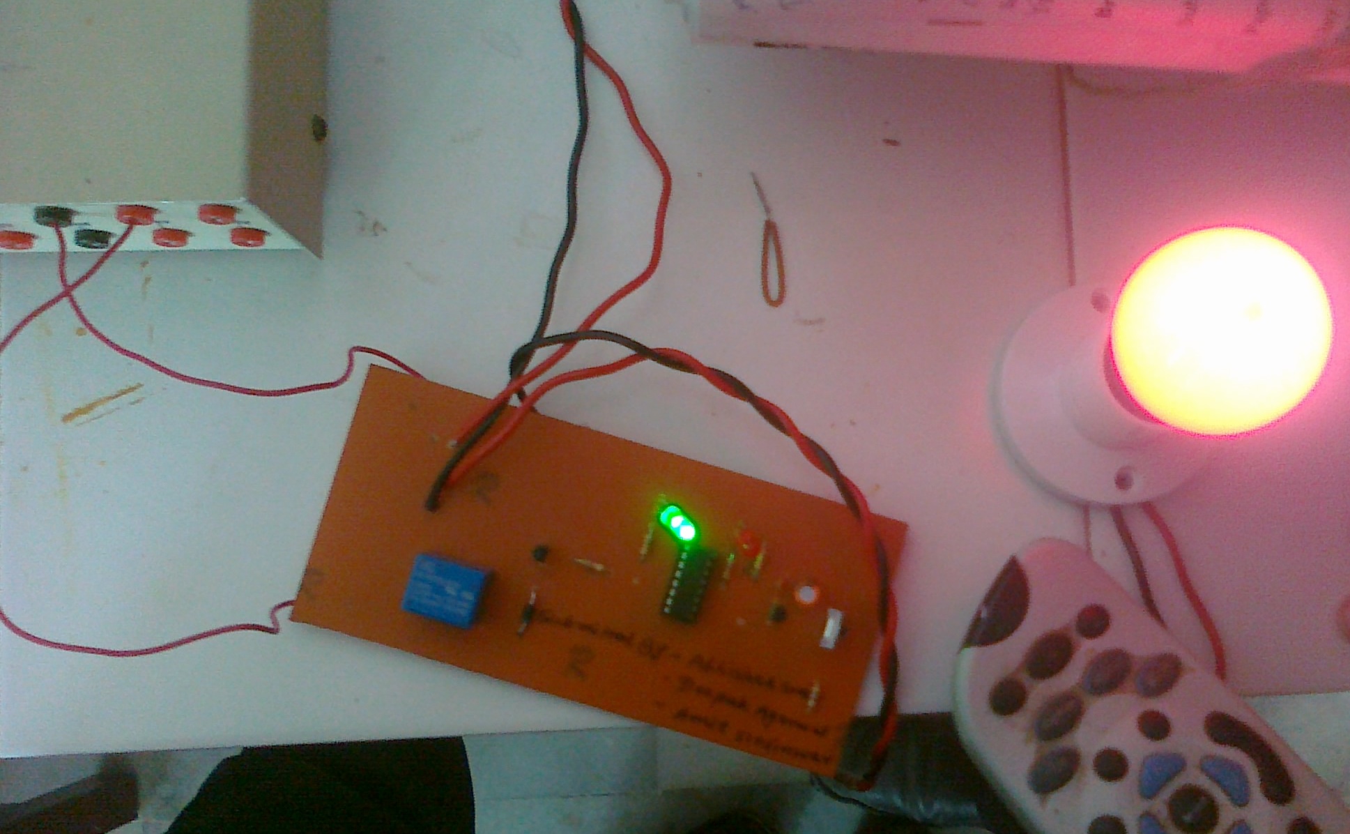
AFTER COMPLETION:


WORKING PROJECT:


____________________________________________________________________________

To provide this project a small area here i am giving a small PCB layout of the above design:
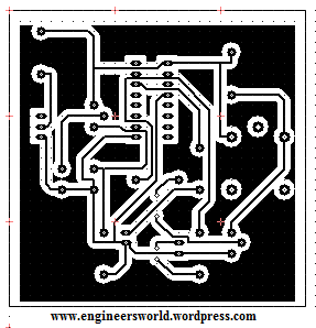
pcb layout


Its a new simplified form of PCB layout of above project.

Thursday, 10 March 2011

Day Finder Software in 'C' Language

Here is the mine designed software of day finder,which gives you the correct day if you just enter the date on any year.It is completely designed in c language and if you want the code of the software you can  mail me or write it here.

Enjoy!!!


To download the software CLICK HERE.

Thursday, 27 January 2011

List of microcontroller based projects

Below is the list of microcontroller based major projects,futher they can be modified too for further enhancement:
1. Artificial intelligent solar power generation

2. A testing method for PIR detectors system

3. A mobile - agent based distributed intelligent control system architecture for
home automation

4. A multi agent multi sensor based security system for intelligent building

5. Industrial energy saver

6. A novel optimum point tracker of the solar cell power supply system

7. Train collision detection

8. Humidity monitoring and pumping system

9. Alcohol detection with vehicle controlling

10. Automated restaurant for efficient maintenance

11. RF based human movement monitoring

12. Smoke alert system for industries

13. Intelligent guard alert system

14. Auto-image monitoring using CCTV camera

15. Path planning system for blind

16. Digital energy meter with auto limiting of load

17. Intelligent fire detection and fighting robot

18. Temperature level monitoring and automatic control in boiler

19. Self guided vehicle

20. Automated conveyor system

21. Modern car parking system

22. Ozone gas generator for water purifier

23. Aeronautical collision prevention system

24. Automated bus-stop alert for passengers

25. Bus identification system for blind

26. Eye blink with more explanation

27. Wireless motor control system

28. Chopper based dc motor controller

29. PWM based solar tracking system with sine wave inverter

30. PWM based single phase ac induction motor with close loop controller

31. PWM based three phase ac induction motor with close loop controller

32. Single axis solar panel tracking system

33. Double axis solar panel tracking system

34. Solar based lighting system

35. Solar agro sprayer

36. Coil winding machine

For further information over any project,write us here,soon we will try to update over it.

Monday, 17 January 2011

Intranet Chatting:Project

Project Courtsey by mayank khandelwal (mkdudes@gmail.com)

This Project Entitled as ‘INTRANET CHATTING’ is used basically for chatting purpose with the remote clients or users on Internet or local networks. Here in this project a java client / server combination is used to chat with remote users. When a Client wants to chat with a user on a remote host, he sends a   request to the Server with a identification name like chat-id, the server responds to the request by identifying the client-id which is already registered in the server domain and when matched his request is granted and the client can begin to chat with the remote users present on the internet or local network.

The power of Internet is such that it integrates together LANs located across diverse software and hardware forms into a single large communication network that spans the globe. The client needs to have a client software such as Netscape Navigator or Internet Explorer to retrieve information   as well as chat on the

www.  WWW is referred to as Netsurfing. And it supports chatting, text, video and audio.

The benefit of using “INTRANET CHATTING” over other chatting tools is that, with the help of java, the programmer can create applet applications which can be use the internet as a server. Applets are machine independent and so java programs can run on any computer on the internet.

The term client/server is used in the context of networking, what it actually means.

It is important to understand the terms client/server because the INTRANET CHATTTING project is supported completely by client/server model. A server is anything that has some resource that can be shared. There are compute servers, which provide computing power, web servers, which store web pages. A client is simply any other entity that wants to gain access to a particular server. The interaction between client\server is like an interaction between an electrical socket and a lamp. The server is a permanently available resource while client is free to “unplug” after it has been served.

The program's premier feature is its whiteboard drawing utility. You can draw freehand, do circles, squares, lines, text, or paste image files to the canvas.  This is ideal when users want to "sketch" concepts for one another.  Users can interact publicly with everyone else on the server, or they can chat/draw privately using java Chat's "whisper mode".  Users can create and manage chat rooms, which can be either "public" or "private".  The server will also store and manage answering machine-style messages for users who aren't online, and instant messages can be sent to those who are.  Additionally, users who aren't watching their screens can be paged with sound.

To download the entire project


Password     ewd

Wednesday, 5 January 2011

Variable Regulated Power Supply:Project

Variable Regulated Power Supply The project “VARIABLE REGULATED POWER SUPPLY” plays a very important role in the laboratory functions and that is mainly to the electronics labs. As in electronics all the instruments, components work on a particular regulated dc supply ,so a project which can provide this supply by converting the alternating current to direct current that too into a great range of regulated power keep its own preference. As it can produce a range of 0-30 v direct current by regulating and converting alternating current is has a vast application too. Such converters are also known as "Switch Mode Power Supply" (SMPS). AC to DC converters generally comprise a rectifier bridge to rectify the AC current of the input line and a regulating device supplying on output of one or more regulated DC voltages.

Just the simple ac current is applied and through potentiometer you get the desired regulated dc power supply.

Variable Regulated power Supply

Following is the list of parts or the components required to design this circuit:


1.      BR1 = Bridge Rectifier, 100V - 3A

2.      C1 = 2200 µF, 63V

3.      IC1 = LM317, adjustable regulator

4.      C2 = 0.1 µF

5.      V = Meter, 30V, Ri = 85 ohm

6.      C3 = 1µF, 40V

7.      TR1 = Transformer, 25V, 2A

8.      Plug = 3-wire plug & cord

9.      R1 = 18K, 5%

10.  S1 = On-Off toggle switch

11.  R2 = 220 ohm, 5%

12.  D1 = 1N4001

13.  R3 = 27K, 5%

14.  Fuse = 110V, 500mA, slow-blow

15.  P1 = 5K, potentiometer

16.  P2 = 10K, 10-turn trim-pot

17.  Fuse Holder, wire, solder, case, knob for P1

18.  Red & Black Banana Jacks

WORKING:-

The 110V-AC coming from the powercord is fed to the transformer TR1 via the on-off switch and the 500mA fuse. The 30v ac output (approximately) from the transformer is presented to the BR1, the bridge-rectifier, and here rectified from AC (Alternating Current) to DC (Direct Current). If you don't want to spend the money for a Bridge Rectifier, you can easily use four general purpose 1N4004 diodes. The pulsating DC output is filtered via the 2200µF capacitor (to make it more manageable for the regulator) and fed to 'IN'-put of the adjustable LM317 regulator (IC1). The output of this regulator is your adjustable voltage of 1.2 to 30 volts varied via the 'Adj' pin and the 5K pot meter P1. The large value of C1 makes for a good, low ripple output voltage.
Why exactly 1.2V and not 0-volt? Very basic, the job of the regulator is two-fold; first, it compares the output voltage to an internal reference and controls the output voltage so that it remains constant, and second, it provides a method for adjusting the output voltage to the level you want by using a potentiometer. Internally the regulator uses a zener diode to provide a fixed reference voltage of 1.2 volt across the external resistor R2. (This resistor is usually around 240 ohms, but 220 ohms will work fine

without any problems). Because of this the voltage at the output can never decrease below 1.2 volts, but as the potentiometer (P1) increases in resistance the voltage across it, due to current from the regulator plus current from R2, its voltage increases. This increases the output voltage.
D1 is a general purpose 1N4001 diode, used as a feedback blocker. It steers any current that might be coming from the device under power around the regulator to prevent the regulator from being damaged. Such reverse currents usually occur when devices are powered down.
The 'ON' Led will be lit via the 18K resistor R1. The current through the led will be between 12 - 20mA @ 2V depending on the type and color Led you are using. C2 is a 0.1µF (100nF) decoupler capacitor to filter out the transient noise which can be induced into the supply by stray magnetic fields. Under normal conditions this capacitor is only required if the regulator is far away from the filter cap, but I added it anyway. C3 improves transient response. This means that while the regulator may perform perfectly at DC and at low frequencies, (regulating the voltage regardless of the load current), at higher frequencies it may be less effective. Adding this 1 µF capacitor should improve the response at those frequencies.
R3 and the trimmer pot (P2) allows you to 'zero' your meter to a set voltage. The meter is a 30Volt type with an internal resistance of 85 ohms. I you have or obtained a meter with a different Ri (internal resistance) you will have to adjust R3 to keep the current of meter to 1mA. Just another note in regards this meter, use the reading as a guideline. The reading may or may not be off by about 0.75volts at full scale, meaning if your meter indicates 30 volts it may be in reality almost 31 volts or 29 volts. If you need a more precise voltage, then use your multimeter.