VARIABLE REGULATED POWER SUPPLY--PROJECT
________________________________________________________________________________________________
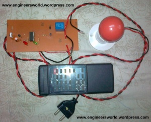
A combined project by Abhishek, amit and me.
Following is the list of parts or the components required to design this project:
- IR receiver module TSOP1738
- Transistor T1 (BC558)
- Decade counter IC CD4017 (IC1)
- LED1 (red)
- LED2 (green)
- Transistor T2 (BC548)
- Relay RL1, 5V, 100 ohm
- Diode 1N4007 (D1)
- R1 = 220K
- Bulb Holder
- Bulb
- R2 = 330 ohm
- R3 = 1K
- R4 = 330 ohm
- C1=100 uf,16V
- C2=0.1 uf
- 5V dc supply
- Soldering Iron ,Solder wire
- PCB Designing Material
- 2 Pin plug
- Wires
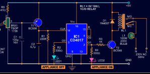
Connect this circuit to any of your home appliances (lamp,fan, radio, etc) to make the appliance turn on/off from a TV, VCD or DVD remote control. The circuit can be activated from up to 10 metres.The 38kHz infrared (IR) rays generated by the remote control are received by IR receiver module TSOP1738 of the circuit.
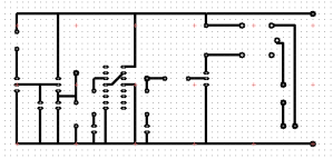
PCB LAYOUT :
CIRCUIT DIAGRAM:
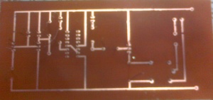
AFTER COMPLETION:
WORKING PROJECT:
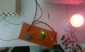
____________________________________________________________________________
To provide this project a small area here i am giving a small PCB layout of the above design:
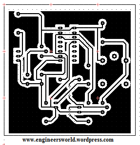
Its a new simplified form of PCB layout of above project.
hey guys isnt the relay position in the layout wrong.......shouldnt the centre hole be towards left side
ReplyDeleteNice project. If you have provided with working principle it would be better....
ReplyDeleteIf I would like to control more than one devices by remote control then what changes I have to do in above circuit?
ReplyDeletehello ashvi,
ReplyDeletein this case you can just connect them between the two wires with which i have connected the bulb in the series, but in that case all devices will turn on and off simultaneously!! You won't be able to control them individually!!
thanx
yes Zahid you are correct, this problem occurred during our project which i solved by correcting the error.
ReplyDeleteFor this i am providing a new PCB layout.
Soon i will try to update over it.thanx!!
ReplyDeleteis the circuit working properly..//////
ReplyDeletecan u give the concept behind designing
ya its working properly....!!!!
ReplyDeletethis is the real project made by me and my team mates.
Well about the principle i will soon update it....!!!
how ll i know the 1,2,3 terminals of tsop1738 to connect it in the circuit
ReplyDeleteWell that is something which is done by observing IC in correct position,well for starting you can download the datasheet of Tsop1738....just google datasheet tsop173.
ReplyDeleteIf you still unable to find just comment here.....
hi,can this system be modified to control more than one lamps in parallel ?
ReplyDeleteif so,how?
how the diode 1N4007(D1) works?
ReplyDeleteI workd on this project an successfully i got the output...... Will u plz send me the documntation, discription, explanation how this actually function.....and works
ReplyDeletehow to find whether the TSOP 1738 is sensing the IRsd or not?
ReplyDeletewe are currently doing a project on remote operated master switch which controls only lamp. we need to know how to connect the relay and how to identify TSOP1738 sensor is working or not?
ReplyDeletei am having 5volt spdt relay which contains 5 terminal..how can i connect?..reply plz
ReplyDeletei made the circuit but while using it i found out that if we are operating something else like tv etc with remote, the appliance connected with the remote control circuit also turns on and off. any solutions?
Deletei made the circuit in which i use led instead of relay for checking the circuit is working or not..it works for me..i am having 5volt relay and i am having 5 volt supply coil not energised..how many milliAmpere is needed for the relay to energise...plz help me
ReplyDeleteits working...i am happy..hi shruthi i can tel u abt relay wiring..spdt relay has 5 terminal in that 3 terminals and closer and 2 terminal are seperate..in that 3 terminal centre one is common and the left,right are coil to give 5volt supply..
ReplyDeletei made this project but the leds get on when i press the remote and as i release the remote switch the leds become off . why/
Deleteif ur circuit is perfect green led glows by pressing remote button..thats the way to check ur sensor..
ReplyDeleteif ur circuit is perfect red led glows by pressing remote button..thats the way to check ur sensor..
ReplyDeletecircuit working perfect..
ReplyDeletehi deepak _ i wanna know on the resistors like if you check your diagram R3 = 1K is that an 4band or 5 colours...sorry your picture qlty. i cant see..... i would like to know on R3,R4,R2,R1 and R5 are they all 4 band colours - sorry i am an beginner on this>>>johan
ReplyDeleteHi everyone
ReplyDeleteI need your help.... All the resistors are they all in 4 colour band or 5..... Thanks johan
Hello Mr.Deepak
ReplyDeleteYour project is very nice ,but My circuit has some wrong,when i connect it power green led is light and relay not working,(there is not voltage in transistor BC 548)Please explain what wrong with me.Remote signal is worked.
Tks
Sampath
Voltage on pin 3 goes to zero when TSOP receives IR rays at 38 khz....If u connect LED with 1K resistor between pin no. 2 nd 3 of TSOP 1738 it will blink fastly when TSOP receives IR rays
ReplyDeleteVoltage on pin 3 goes to zero when TSOP receives IR rays at 38 khz….If u connect LED with 1K resistor between pin no. 2 nd 3 of TSOP 1738 it will blink fastly when TSOP receives IR rays
ReplyDeletehey friend i want to know how much this project will cost us.
ReplyDeletecan we use 33 ohm resistor isntead of 47 ohm as R5 and ic cf4017be instead of ic 4017 ?
Deleteya it is possible....Soon try to update it...:)
ReplyDeleteu give ur id i will send u......and thanks for making this project..:)
ReplyDeletenice reply Harsh soni...!!!
ReplyDeleteuse the datasheet...just google it and use, if still facing the problem tell me....!!!
ReplyDeletethanks praksh for solving issues
ReplyDeletethanks prakash for ur feedback...refer engineersworld to ur friends too...:)
ReplyDeleteu can see the verification of resistors in ckt diagram... if still not getting mail be the problem!!!
ReplyDeletecan u mail me exact problem with picture of pcb and circuit....
ReplyDeletefor me it cost just rs 150......
ReplyDeletehi i want to make this project. i am a first year electronic eng. student.
ReplyDeleteactually my pblm is that how there is connection proceed between tsop and transistor mens how it make its base high and low, by pressing remote button. please explain me. give me complete discription as i dont know much about electronic devices. please.....
hello arvind do one thing google and download the datasheets of tsop , transistors and aything which is leading you in confusion...and soon u will get everything by your own.
ReplyDeleteIn case you still face any problem, don't hesitate sharing it.
Though it is shown that how the relay is connected in the circuit , can you plz upload the 5v relay photo( relay that is brought from the shop) showing which pin is n/o , comm. etc
ReplyDeletegoogle the image ..its very common type of relay
ReplyDeleteplease i need the block diagram of the circuit also i need the literature review of the project
ReplyDeletei did the circut but once i off off the circut using a remote i cant on it back
ReplyDeletewhat is the purpose of the decade counter in the circuit...? is it possible to use just a D-flip flop? the project didn't work at first when we implemented it on a bread board, but when we removed the pnp transistor from the circuit, it worked, why's that so?
ReplyDeletecan we use ic cf4017be instead of ic cd4017 and 33 ohm resistor instead of 47 ohm as R5 ? btw what is the difference between cf4017 and cd4017 ?
Deleteur id ??
ReplyDeletehello.. i searched the datasheet of relay but i have didn't get from internet.... plzz sent me the datasheet of relay
ReplyDeletehello.. i searched the datasheet of relay but i have didn’t get from internet…. plzz sent me the datasheet of relay
ReplyDeletehi deepak
ReplyDeletemy name is ajay and i am make this project but it not work properly
pls tell me what the problem in my project
the green led is on but when i press remote batten then no change..........
hi deepak
ReplyDeletemy name is ajay and i am make this project but it not work properly
pls tell me what the problem in my project
the green led is on but when i press remote batten then no change……….
my e-mail id: ajay159lamba@gmail.com
i have a new problem circut is not working properly i press and hold the batten of remote then led is on otherwise automatic off after 1-2 second
ReplyDeletethen its the problem of relay , check the circuit connections and if necessary change the relay.
ReplyDeletei press the remote batt. then red led is on and green is off but after 1- 2 sec. automaticli green is on and red led is off pls tell me what is problem in my circut
ReplyDeletehey hi deepak, i'm aman, actually i want to make this project. so can you guide me, please send me all component list for making it or it is possible to increase number of switches, sleep mode but without using microcontroller. and please send me the pcb layout too.. thanks in advance :)
ReplyDeletehey friends pls explain me how can i know the terminals of the relay????????
ReplyDeletein my circuit pin 2 goes high initially and led glow but after pressing remote switch it start working properly. so why pin 2 is high initially instead of pin 3. if any change require pls tell me soon…its urgent..
ReplyDeletechange the relay load connection pin.
ReplyDeletepin 2 goes high then led is on and relay is on but relay load connection pin is connect properly otherwise relay not work properly
change relay out pin.
type on google
ReplyDeletefiletype:pdf datasheet relay no
did u got the solution ajay!!!
ReplyDeleteya . ple tell me that can v use c2 0.01 uf (103) place of c2 0.1uf (104)
ReplyDeleteDEEPAK WE CONNECTED THIS PROJECT ,OUR SENSORS IS GOING TO PERFORM WELL BUT RELAY DOES NOT WORK PROPERALY ......... ALSO WE CONNECTED 60 WATT LOAD TO THE OUTPUT WHY THAT HAPPEN?
ReplyDeletehi.....tis is mail id...
ReplyDeletevjylovesu@yahoo.com
can u pls mail me the ppt for tis project....?
hi......can u pls mail me the ppt for tis project….? plz deepak..
ReplyDeleteI have same problem, green led is on and Relay tuns on when connected to 5v. It should be red by default so when ir transmits it should change to green.
ReplyDeleteTSOP1738 is not available in market so any receiver can be used instead of this ?
ReplyDeletecan IR TK19 423 be used to replace the TSOP1738 receiver?
ReplyDeletesir.Can i use simple ir led receiver instead of tsop1738 receiver module,yes or no?and why?
ReplyDeleteyes dude!!!
ReplyDeletehey am geff,can you send me the all infomation of this project to geoffrykip@yahoo.com
Deleteuse IR TK19 423
ReplyDeletesorry for late reply bro...did u still need that dude!!!
ReplyDeleteThanxxx Dearr
ReplyDeleteis the position of relay in layout wrong.......please reply it's urgent
ReplyDeletecan i use a +6V relay.........becoz +5V relay is not available in market, and what to use for a +5V dc supply.
ReplyDeletehey which relay is this SPDT or DPST
ReplyDeleteplease reply....
my email id is rubindevasia@gmail.com please tell mee how to make this i need it urgently do reply........
ReplyDeletesir plz connect with me mansoor_ali533@yahoo.com i m making ths project but not working properly no remote is matching with sensor plz and gve me complete litreture
ReplyDeleteplz sir im wtng for u mansoor_ali533@yahoo.com gve me data
ReplyDeleteHi deepak i am using 7805 after relay ...it works well....for 4017 & ir sensor health....
ReplyDeleteHi deepak i am using 7805 after relay …it works well….for 4017 & ir sensor health it solve problem of relay ratting..
ReplyDeletei am doing this as my mini project.i had completed the circuit ,but the relay is not energising.iam using a relay having 5 pins .please help me..
ReplyDeleteplz show the components on pcb layout.
ReplyDeleteactually I want the working of the circuit ....I made the circuit bt I need it to explain it to others....PLEASE HELP
ReplyDeleteexcellent
ReplyDeletethanks
ReplyDeletehey i want to do this project but i m quite confusing on ic legs so can you please send me PCb diagram of both sides on my mail dx.patil@gmail.com
ReplyDeletehi,
ReplyDeleteI worked on this project an successfully i got the output…… Will u please send me the documentation, description, explanation how this actually function…..and works to the id vedabkrishna@gmail.com
please asap.
sure bro i will , please send the pictures from your project with your team we will love to highlight them on EWD.
ReplyDeleteKeep reading!!
Hi geff,
ReplyDeleteLet me know if you still need the information!!
hi friend i am interested with this project but i dont know more about electronics can u help me to make this
ReplyDeletethe project is very useful for the home...i also making this project i have a circuit diagarm but i confuse that ic have 16 terminals and this circuyit shows that only connect 8 terminals,,,,,,14, 3, 8, 13, 2, 4, 15, 16....so...then other terminals open or sort..please send me nearly connected ic photo pf your circuit...
ReplyDeleterelay haS 123456 & A, B PIN...WHAT PIN USE FOR ACROSS OF DIOD OR WHAT PIN USE FOR NEUTRAL & LIVE..PLEASE ANSWER..IMMEDIATELY..
ReplyDeleteall circuit is complete working but sensor is not working what i do?
ReplyDeleteWhat is an equivalent transistor for a BC558?
ReplyDeletehi guys, i am confused for how cd4017 recognize the IR receiver, plse help me
ReplyDeletehi... this project can i used to stop my electrict meter?my house 14 meters far from the post.pls.reply
ReplyDeletehii deepak.
ReplyDeletemera naam gaurav h mene ye project bnaya h but uski project report ni mil rhi h kya ap pls mjhe help kroge......
my email id is grvskl@gmail.com
ReplyDeletekya me 5v relay ko direct 230 ac de sakta hu.....
ReplyDeletemy email id is grvskl@gmail.com
ReplyDeleterelay is operate only 5v, if you will give 230 may it is destructed, but in relay 230 AC v be pass to switching the voltage.
ReplyDeletethank you
how can we use ic cf4017be instead of ic cd4017 in this circuit ? if any modifications will be needed plz specify.
ReplyDeleteI have done this thing, and output is done but when it has been on first time, automatically output came before I click any remote buttons. can fix it
ReplyDeleteI have done this thing, and output is done but when it has been on first time, automatically output came before I click any remote buttons. can u fix it
ReplyDeletehey i want to do this project but i m quite confusing on ic legs so can you please send me PCb diagram of both sides on my mail suganyaksrv@gmail.com
ReplyDeleteplease send me the ranges of input voltage and current
ReplyDeletewhat will be the output of tsop 1738
ReplyDeleteI made this circuit but its not working, only red led is glowing red whata could be the problem?please help
ReplyDelete